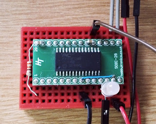
 |
| Minimal PIC32MX150 setup! |
I've temporarily remove the download link, as I've managed to introduce an issue with the PPS mapping. This causes PPS mapping to fail. Once I've fixed this, I'll put the files back up again.
In order to use these files, you'll need to download them first. Once you've downloaded them, place the Reversatronics_MX150 folder into the mpide-0150\hardware\pic32\variants directory of your MPIDE environment. This adds in the board definitions for MPIDE to use. You will need to restart MPIDE if you already have it open. Then, using your favourite programmer tool (pic32prog, MPIPE or whatever tools you use) and programmer, write the Reversatronics_MX150.hex file to your PIC32MX150 device. Now you should be the proud owner of a PIC32MX150 with the avrdude bootloader on it!
If you want to experiment, then the basic connections for the device will look like the following:
It is important that all power pins are connected, including the analog supply pins AVDD and AVSS. There's a bunch of decoupling capacitors shown, and a couple of pullup/down resistors. Choose something suitable from whatever parts you have to hand.
Once you have everything set up, you should be able to hold the PGM button down, and power up the circuit. If everything works as it should, you should be greeted with a blinking boot LED. Assuming you have a 3.3V serial adapter connected to the RX/TX pins, you should now be able to upload a blink test sketch or something similar to ensure that communications works correctly.
In an attempt to make things a bit more understandable, I've put together a little table of what lives where. Note that PPS enabled pins are grouped into one of four groups, and there's a table of which group contains which functions. If you want to use alternative functions, you need to use the mapPPS() function to switch what the pin is doing.


No comments:
Post a Comment