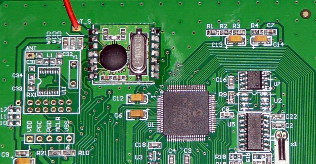
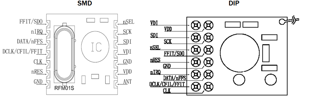
Helpfully the connections for both the SMD and DIP modules are connected together, so we have an easy place to tap the signal without having to even solder anything! Lastly, the silkscreening for the seperate components seem to be for RF Monolithics RXC101 so CurrentCost could have the choice of two different RF modules, or place the components direct on the board. Yes, this does mean that the RFM01 module uses the RXC101. On another aside, you might note that there's a programming connector with silkscreen next to it - this is the same pinout as the CurrentCost Dev board, so I could have saved myself some time by looking at this rather than reversing the connections!
DIP (pin num)
|
Bus Pirate
|
SDI (3)
|
MOSI
|
SCK (4)
|
CLK
|
nSEL(5)
|
AUX
|
SDO (6)
|
MISO
|
GND (8)
|
GND
|
Now we can use the SPI sniffer on the Bus Pirate to observe messages that are received, testing with a real CurrentCost device first of course! This is done in exactly the same way as sniffing the SPI bus in the previoud Part 2.5.
Now we can get on with coding! Basically, once we start to transmit, the transmitter will pulse it's nIRQ line each time it wants a new bit. All we need to do is supply the bits! One thing I discovered from reading the RXC101 datasheet (page 15) is that all transmissions have to start with a preamble (0xAA) and then a sync word (0x2DD4), which is hard coded. Without this, the receiver will not receive the message - I know, I tried without to begin with!
Building on the code we had previously (step 3), I added a bit more. I'm not reproducing the code from before, as it'll simply take up space.
// Data to transmit
uint8_t txBuffer[8] = { 0x01, 0x02, 0x04, 0x55,
   0xAA, 0x04, 0x02, 0x01 };

void main() {
 InitRadio();   // Configure the radio
 TXData(txBuffer);  // Send the data!

 while(1);   // Stop!

}

// Transmit the datablock
void TXData(unsigned char *txBuff) {
 uint8_t cnt;

 StartTX();   // power up the TX
 __delay_us(100);

 SendFSK(0xAA);   // Transmit header
 SendFSK(0x2D);   // Sync word
 SendFSK(0xD4);   // Sync word

 for (cnt = 0; cnt<9; cnt++) {   // data packet
  SendManFSK(txBuff[cnt]);
 }
 WaitFSK();   // wait for last bit to be transmitted
 StopTX();   // Turn off TX
}

// Manchester encode and send one byte
void SendManFSK(uint8_t data) {
 uint8_t cnt = 8;
 while (cnt--)
 {
  if (data & 0x80) {
   Sendbit(1);
   Sendbit(0);
  }
  else {
   Sendbit(0);
   Sendbit(1);
  }
  data <<= 1;
 }
}

// Send raw FSK byte - not manchester encoded
void SendFSK(uint8_t data)
{
    uint8_t cnt=8;
    while (cnt--)
    {
        if (data & 0x80) {
            Sendbit(1);
        } else {
            Sendbit(0);
        }
        data <<=1;
    }
}

//  Sends one bit of data
void Sendbit(uint8_t data) {
 while (!nIRQ);   // wait for nIRQ to toggle
 while (nIRQ);   // high then low (1.6uS)
 FSK = data;
}

// Wait for nIRQ before stopping TX
void WaitFSK(void)
{
 while (!nIRQ);   // wait for nIRQ to toggle
 while (nIRQ);   // high then low (1.6uS)
}
The observant reader might notice the sudden appearance of Manchester encoding, and be wondering where this came from. I'd come across some code written by GanglionTwitch, which was for a DIY radio receiver for CurrentCost sensors. This code can be found at http://gangliontwitch.com/ccPower.html. Knowing the data is manchester encoded is a great help, although I have no idea why it is encoded in such a way. The TX and RX modules already synchronise, so I can only presume it was a hangover from a previous iteration of code that needed some form of clock sync. Manchester encoding has the advantage of transmitting both data and clock signals together, but takes twice the bandwidth to do so.
After compiling the code I uploaded the output to the CurrentCost Dev Board, started the SPI sniffer and powered up the Dev Board. The result? Absolutely nothing! Somewhat disheartened, I used my radio to listen for a transmission, and I could definately hear RF coming out. I went through my code and didn't spot any obvious issue. I spent a great deal of time trying to figure out what's going on. Eventually, I put an oscilloscope on the inputs to the transmitter and discovered that sometimes the code was missing the nIRQ request for the next bit . I then disassembled the code that'd been produced, and things make a bit more sense... The two nice simple while statements turned into something like the following assembly:
WaitFSK: GOTO LoopA
LoopA:  BCF STATUS, 0x5
  BCF STATUS, 0x6
  BTFSS PORTA,0x2
  GOTO nxtA
  GOTO nxtB
nxtA:  GOTO LoopA
nxtB:  GOTO LoopB
  GOTO LoopB
LoopB:  BTFSC PORTA, 0x2
  GOTO nxtC
  GOTO nxtD
nxtC:  GOTO LoopB
nxtD:  GOTO Done
Done:  RETURN
I don't expect people to know PIC16 assembler, so just as explanation here: BCF uses a single instruction cycle, BTFSS/BTFSC uses one or two cycles, and GOTO always uses two cycles. That's 16 instruction cycles at a minimum to get through the code. Given the PIC uses 4 clocks cycles per instruction, and the default clock is 4MHz, the outcome is that the code isn't able to always capture the nIRQ activation and hence sometimes misses it. I took a twofold approach to fixing this - I increased the clock speed to 8MHz, and I made Sendbit() and WaitFSK() more streamlined by resorting to assembler:
//  Sends one bit of data
void Sendbit(uint8_t data) {
#asm
    sla:
        BTFSS 0x5, 0x2      //while(!nIRQ);
        GOTO sla
    slb:
        BTFSC 0x5, 0x2      //while(nIRQ);
        GOTO slb
#endasm
        FSK=data;
}
// Wait for nIRQ before stopping TX
void WaitFSK(void)
{
#asm
    wla:
        BTFSS 0x5, 0x2      //while(!nIRQ);
        GOTO wla
    wlb:
        BTFSC 0x5, 0x2      //while(nIRQ);
        GOTO wlb
#endasm
}
Compiling and uploading this code to the CurrentCost Dev board results in some action from the receiver - now the data I put in the txBuffer[] turns up at the receiver! As I'd captured a real packet from one of the spare CurrentCost Dev Boards, I was able to populate txBuffer[] with real data, and see the effect of transmitting it on the CurrentCost receiver. Now I can monitor the received data at the receiver, and I can transmit whatever data I want. This makes it possible to take apart the Current Cost protocol (C2) if you want to!
No comments:
Post a Comment